
SR1309 UV Tube Flame Sensor for R9454 Replacement Evaluation
SR1309 is a UV tube flame sensor with a published spectral response range of 185–260 nm. For projects evaluating alternatives to Hamamatsu R9454, review the tube specifications, external driving circuit, mechanical installation and flame-controller requirements before selecting a sample. Model references identify the scope of an engineering evaluation. They do not establish interchangeability or approval for a particular burner or flame-safety system.
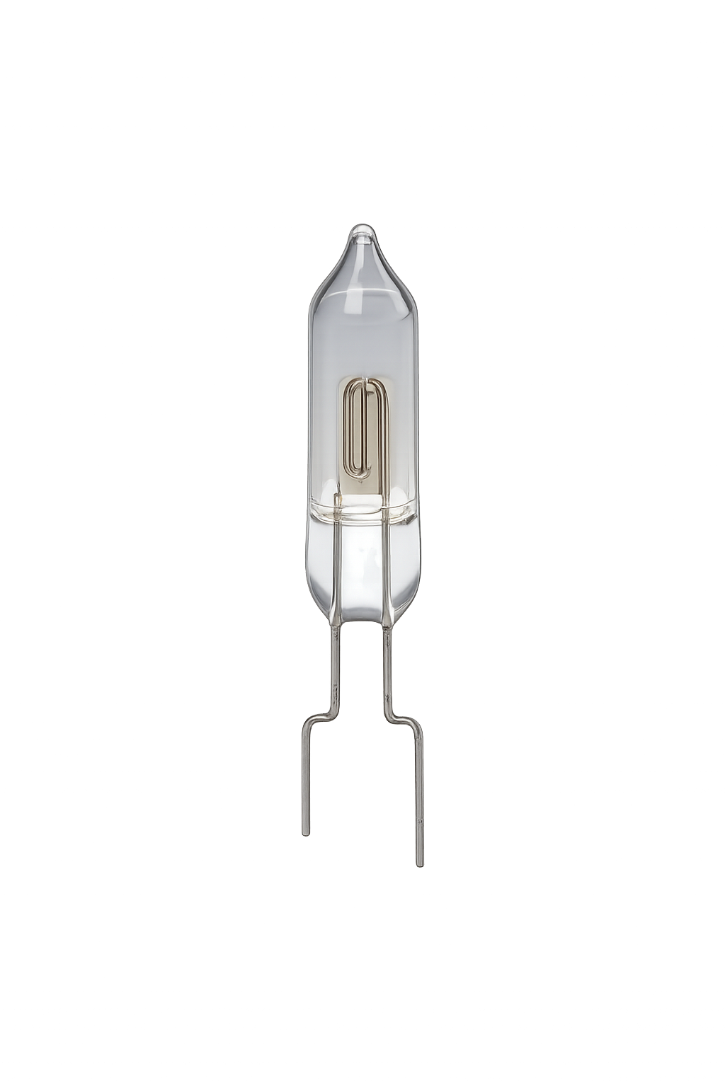
Key Features
- Published spectral response: 185–260 nm
- Model-specific working voltage and discharge parameters
- Pulse output via the illustrated external driving circuit
- Candidate for R9454 replacement evaluation after application review
Typical Applications
- Industrial gas burners
- Combustion monitoring systems
- Boilers and furnaces
- Industrial safety and flame supervision systems
Technical Overview
For R9454 replacement evaluation, review the tube specifications, external driving and quenching circuit, mounting, viewing arrangement and controller requirements. Model references do not establish interchangeability or approval for a particular flame-safety system.
Published SR1309 Specifications
| Model | SR1309 |
| Spectral response range | 185–260 nm |
| Power supply voltage (DC), working parameter | 400 ± 25 V |
| Average discharge current, working parameter | 0.3 mA |
| Quenching time, minimum | 1 ms |
| Discharge starting voltage (DC), maximum | 360 V at 25°C |
| Continuous discharge voltage (DC), typical | 300 V at 25°C |
| Signal path in the illustrated working circuit | Pulse output via an external driving circuit |
Values above are taken from the SR1309 sheet currently linked by this website. Confirm the latest datasheet revision and the required operating conditions for your project. Recommended working conditions and maximum ratings are different; the 500 V maximum supply rating shown in the sheet is not the recommended operating voltage.
The illustrated circuit includes the external components used to obtain a pulse output. This does not specify a direct TTL output, fixed pulse amplitude or a ready-to-connect controller interface from the bare tube.
R9454 Replacement Evaluation Checklist
| Original component | Exact R9454 version and whether the request concerns a bare tube or a complete detector assembly |
| Driving and quenching circuit | Applied voltage, circuit diagram, quenching arrangement and current limits |
| Mechanical fit | Drawing, pin arrangement, mounting, viewing direction and available installation space |
| Controller or amplifier | Manufacturer, exact model, wiring and required input signal |
| Application conditions | Fuel, burner arrangement, expected flame signal, ambient conditions and maintenance requirements |
| System validation | Application tests and acceptance criteria defined by the system owner before a replacement is approved |
This evaluation checklist does not establish interchangeability and does not assign Hamamatsu specifications to SR1309.
Application Review
For burner, boiler and furnace flame-monitoring projects, share the original tube and controller model together with the circuit and installation details. Detector suitability depends on the complete optical, electrical and control-system arrangement.
R9454 System Review
For R9454 replacement evaluation, review the tube specifications, external driving and quenching circuit, mounting, viewing arrangement and controller requirements. Model references do not establish interchangeability or approval for a particular flame-safety system.
FAQs
Can SR1309 replace Hamamatsu R9454 directly?
What voltage is listed for SR1309?
Does the bare tube provide a TTL signal?
Is this download also a datasheet for SR1406?
Related Sartec Photoelectronics UV Flame Sensors
Request SR1309 Replacement Evaluation
Send your original sensor model, controller or amplifier model, circuit or wiring diagram, mounting information and application requirements.
SR1309 Engineering Review Resources
Concise selection notes for engineers, buyers, and maintenance teams before sampling or replacement review.
For SR1309 replacement evaluation, review the original R9454 component, circuit, installation and controller requirements before sample selection.
Check mounting, viewing arrangement, driving and quenching circuit, controller input and operating conditions. Replacement approval requires validation in the target system.
Related resources include UV tube flame sensors, UV flame detectors, CHECK LIGHT UV flame sensors, and engineering support.
SR1309 UV tube flame sensor - Hamamatsu R9454 replacement evaluation
SR1309 should be reviewed as a UV tube flame sensor candidate for R9454-type flame detection systems. Before sampling, compare operating circuit, flame signal behavior, mounting, environmental limits, and controller compatibility.
Parameters to confirm before RFQ
- Original tube model and controller
- Operating voltage and circuit conditions
- Mounting dimensions and viewing geometry
- Required flame response and false-signal tolerance
Replacement evaluation boundaries
- Replacement approval should be based on system validation.
- Burner management safety logic must be reviewed by the system owner.
- Do not assume interchangeability from model naming alone.